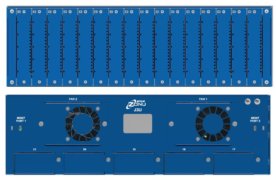
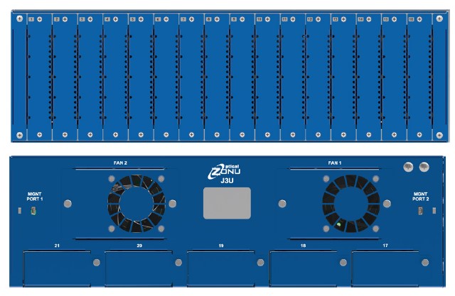
The J3U platform is a 19” 3RU chassis that accommodates (among other things) 16 pluggable, hot swappable fiber optic RF signal tansport modules. Single Slot plug-in modules include the following:
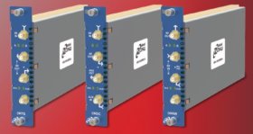
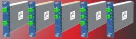
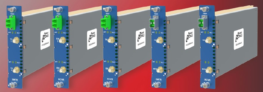
Single Transmitter, Single Receiver, Dual Transmitter, Dual Receiver, Transceiver (Transmitter & Receiver).
J3U transmitters and receivers may be used with J3U RF and Optical Diversity switches to create N+1 and other redundancy architectures.
Digital attenuators (0.5dB steps) enable both transmitter and receiver RF gain control. Transmitters feature linear uncooled isolated DFB laser diodes. Receivers feature high performance InGaAs photodiodes. The standard transport RF frequency band is 30 – 3000 MHz. Options exist for extending the frequency range to 6 GHz on the upper end, and/or 10 kHz on the lower end.
Modules are optimized for linear signal transport with high spur free dynamic range (SFDR). User or programmable adjustable transmitter and receiver RF gain accommodates optimization of noise figue, linearity (P1dB and IIP3), and RF gain over a wide variety of optical loss budgets and RF signal levels. The standard RF interface is 50Ω SMA. Other impedance/connector options may be available, contact Optical Zonu. A variety of APC optical connector options (SC/APC is standard) are available to maintain low optical refletions throughout the fiber plan.
Single bi-directional links supported by a single fiber ae realized by integrating a WDM within the fiber optic tansceivers. More complex traffic achitectures may be realized by using external rack mount CWDM multiplexers.
Multiple options exist for integrating Bias-Ts into transmitters for the purpose of powering antennas and providing control/biasing to LNBs and BUCs. 13/18V (with or without 22 kHz) biasing is user selectable either on the module or remotely through the J3U management system. Detection of such biasing on the Receiver outputs can be automatically transferred to control a compatible remote Transceiver or eFiberSAT unit. This is a unique feature that only the J3U Transceiver is capable of.
Built-in RF shielding facilitates low EMI/EMC/RF interference. RF links may also be optimized for transporting low phase noise reference clocks in the frequency range 10 – 200 MHz.
RF signal transport modules within the J3U platform may be monitored and controlled via SSH, Web UI, OZC GUI, and SNMP v2 and v3.
J3U modules are also available incorporating Optical Zonu’s patented GPS fibertransport with antenna monitoring and active DC load at the optical receiver output port. See US 10,257,739 Bl